Power Sensor
TLDR: I made a current sensor that reports over cellular network to the Internet, providing a summary webpage and email alerting for when the current dies.
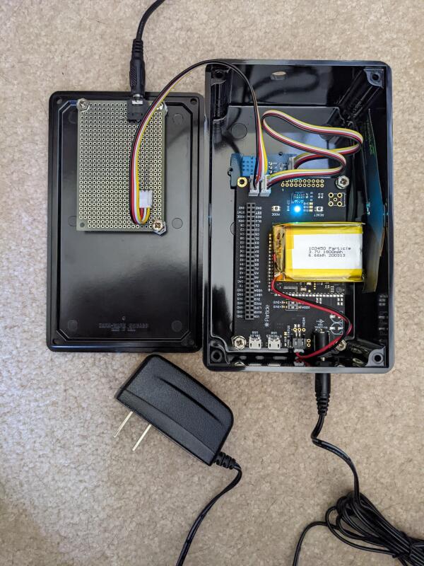
The inside of the finished project.
My parents have a house in the boonies. They’ve got an above-ground pump in a shack that brings water up from a well and pushes it to a couple other houses including theirs. In the winter it can get quite cold there - cold enough to freeze the pump, and cause all kinds of problems. For some reason the best way to prevent this is to house incandescent lightbulbs right next to the pump in an insulated box. It seems like some better product should exist - like a pump electric blanket, especially as incandescent bulbs are harder to find - but they don’t know of one.
One week this last cold December my dad was spending time closer to my grandmother, but had a feeling - he worried that one of the bulbs went out. He was hours away from the house, but if a bulb was out it would spell thousands of dollars in damages. He had no way to tell except to drive out there and check. Sure enough - the bulb was out. His worry was well-placed. He replaced them and drove back.
He told me this story and I thought - there’s a better way. I’m often an engineer looking for a project, so I started looking for some kind of sensor that could alert him to when the bulbs were out. It might be better to just improve the bulbs-heater solution, but I trust that they’ve looked for better solutions than the heating bulbs and that project doesn’t interest me much anyway. Besides, even if they found some pump electric blanket we would still worry about that breaking.
I couldn’t find a good sensor on the market for a reasonable price. What I was finding was equipment that would be at home in industrial or commercial applications, with customers paying industrial or commercial amounts of money.
Design Goals
I had a few goals:
- Reasonable price - under $200
- Sensor failures must not impact the lightbulbs
- Ideally operates over the cellular network and works in the boonies
- Small size
I wanted something to operate over the cellular network because my parents’ WiFi was extremely limited. They use a little hotspot device. Range is limited, although I plan to fix that. The Internet bandwidth is limited especially when multiple people are using it, or when they exceed their data cap. And occasionally they take the hotspot elsewhere, eliminating Internet out there. Cellular network connectivity was also very limited, but seemed more reliable long-term if I could get it to work at all.
It would be bad if the introduction of the sensor increased the possibility that the lightbulb heater would fail… So, I couldn’t put a current sensor in-line with the bulbs. A temperature sensor inside the insulated pump box might be good, or a photo-sensor inside the box assuming the box doesn’t let daylight in. I was most interested in using a split-core current transformer, though. This seemed like a good way to avoid affecting the heater, remain useful even if they change heating systems, and avoid false-negatives like warm days or daylight entering the box.
Better Build Something…
I couldn’t find anything pre-built, so I set out to build something. I was excited to find Particle’s E Series Evaluation Kit with EtherSIM. For less than $100 and no recurring cell-service charge it was designed to send and receive data with Particle’s cloud over LTE, 2G, or 3G. It has onboard analog and digital inputs and outputs, reporting back to an ARM processor. The dev kit even comes with a battery, cell antenna, and temperature/humidity sensor! I clicked “order” almost as fast as possible.
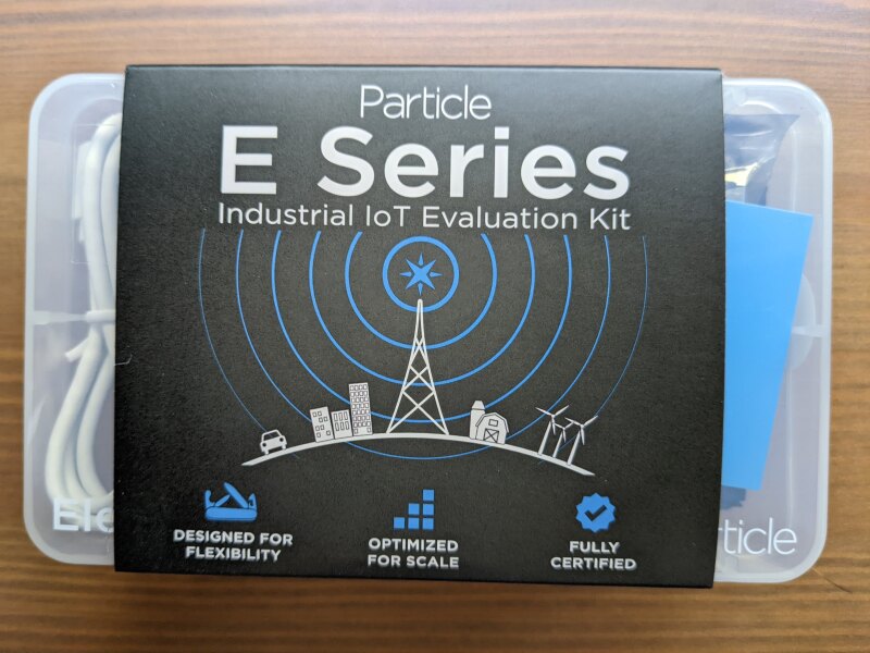
The E Series Evaluation Kit came in a very attractive little package.
Digi-Key had a split-core current sense transformer that looked simple to integrate with the project. It connects via a three-conductor 3.5mm plug, and that seemed nicer to install with than a cable soldered on. I picked that up along with a 3.5 mm jack. Parts arrived quickly.
To experiment with the current transformer, I clipped it around one wire in a lamp’s cord and turned the lamp on. This is a CFL lamp, and should be less current than with the incandescents in deployment. The transformer put out a tiny AC voltage, maybe 4 mV, as detected by my multimeter. The datasheet says it reacts to 0-60 A by outputting 0-1 V, and that it has a turns ratio of 1:1800.
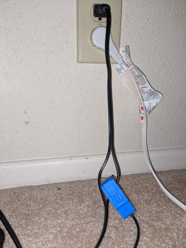
The current transformer on the lamp cord. It doesn’t matter which leg of the cord you have it around.
The way the thing works is essentially that a tube of ceramic and iron (called a ferrite core) is split in half so it can clip around other cables. One part of the core is wrapped with wire. That wire forms an inductor, with the current through its center equivalent to the current in the wire wrapped by the core. That current in the core produces a current through the inductor. A current in an inductor can be a dangerous thing. If the wires on the inductor don’t have a path for current to continue flowing, the voltage will increase very quickly to dangerous levels to try to pass that current anyway. This device doesn’t have that dangerous problem because there must be a resistor built in between the ends of the inductor. I think we can calculate the resistance actually. With a 1:1800 ratio, a 60 A current turns into a 60/1800 A current, or 1/30 of an amp. The output at 60 A is 1 V, so with Ohm’s law, V = I * R, 1 = 1/30 * R, or R = 1 / (1/30), or R = 30 Ω.
I wasn’t sure about the best way to read the AC voltage with the EtherSIM. I didn’t need something terribly accurate because my goal was only to determine whether current was flowing or not - not how much current was flowing. The voltage was so low I didn’t have a good idea how to rectify it, because a diode would eliminate the voltage present. I decided to just plug the current transformer voltage output directly into an EtherSIM analog input, and see how it went. The two problems I see with this setup are that the EtherSIM could be damaged by: the current sensor outputting too large a voltage, or the sensor outputting regular negative voltages. Too large a voltage seems unlikely based on the ampere and voltage rating of the sensor, and that situation would likely only occur when a short or open circuit happened somewhere internal to the project, and I will have to accept that risk. Regular negative voltages will hopefully not be a problem because they are less than even 1 V, and the input impedance on the analog inputs is huge so little or no current will flow.
It still wasn’t clear that the analog inputs could read the voltage quickly enough. US power cycles 60 times per second, so I need to read it more than twice as quickly as that to have a hope of getting reasonable data, and several times quicker than that to get good data. The temperature/humidity sensor takes about 1/4 second to read, so I wasn’t feeling confident. I programmed the EtherSIM to read the voltage as quickly as possible for one second and report back how many measurements it took, and the maximum and minimum values. It reported back a tiny max value, a min value of 0, and that it took over ten thousand samples per second. The analog input is fast enough - it’s about 88 µs per read.
Reading the max input value sufficed for my purposes, so I programmed the EtherSIM to make about 480 voltage measurements in a 1 second period, and then to get the temperature and humidity, and to report that information back along with the battery level and power source. That loop runs every minute. I added in power source and battery level to give some information about whether the power had gone out to the house, and if so how much longer the sensor would report data. This code is available here in “voltage-temp-reader.zip”.
Programming the EtherSIM is extremely simple. Particle provides a web-interface IDE, which starts with C code for setup and loop functions. There’s a button to deploy the code to devices, after which they reboot and run the code automatically. They have a simple tutorial which describes much of the API you need, and the rest is available here. Published data flows back to Particle’s events dashboard, and creating integrations with external services is a snap. I wanted the data from my sensor to route to a service that would display data on a graph, and email alerts when the lightbulbs were unpowered, and Particle supports that with the webhook integration. I set it up to send JSON-format data in an HTTP POST request to a website I created separately.
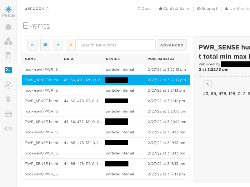
Particle’s events list page makes it easy to see what’s coming from your device in real-time, without additional coding. This is a great prototyping, testing, and debugging resource.
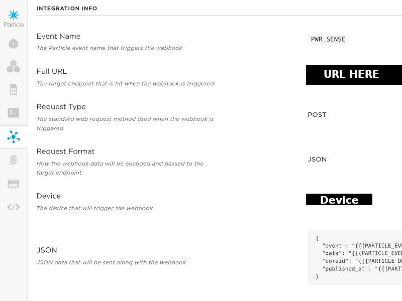
Configuring a webhook is easy, it’s mostly providing the correct remote URL. Particle also recommends some data collection webhook tools that are much simpler than writing a separate webhook handler if your goal is just to analyze some data.
Collecting and Displaying the Data
Many possibilities exist for catching the Particle webhook each time the sensor reports data, but I have an existing server running, upon which I can deploy new code. I built a simple Python webserver which can be configured with pairs of read/write keys, then hosted it in a Docker container behind an Nginx reverse proxy. Particle writes data to my webhook endpoint using one key (which just becomes part of the URL), and a frontend webpage can read the logged data back out using a second key. This two-key setup separates the read and write permissions, because a reader has no knowledge of the write key and a writer has no knowledge of the read key. The keys aren’t as secure as a password and session key setup, but the whole thing is probably secure enough for my purposes. Choose read and write keys that are 20 characters long and random, like passwords. The code for this system is available here in the “webhook_catcher” directory, and may be deployed using the “docker-compose.yml.template” file modified for your purposes. It currently supports only one webhook endpoint, but is setup to easily take many.
Displaying the data requires a frontend webpage that reads out the JSON data and puts it in graphs. I am hosting that on AWS Cloudfront for speed and simplicity. It contains Javascript that reads out the JSON history, processes it a little, and then uses Chart.js to graph the data. The frontend code is in the GitHub repo’s “frontend” directory.
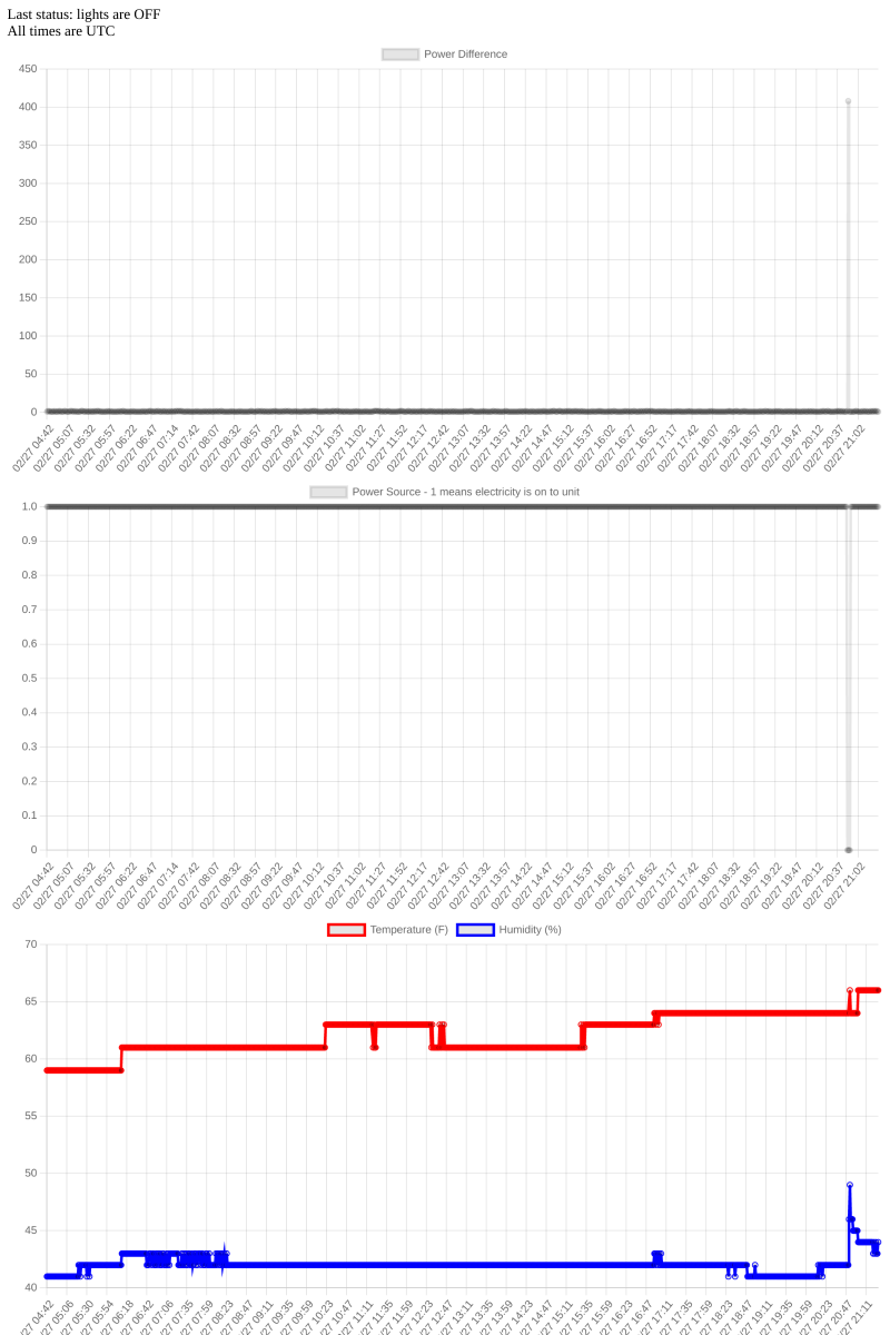
The frontend provides a simple status at the top, and graphs of the data over a recent timescale.
Automated Monitoring
At this point it was possible to check the status of the power regularly, but there’s no automated notification system alerting us when the power goes out. For this I am using an AWS Lambda that runs on a schedule via AWS Eventbridge. This Lambda pulls in the data just like the frontend does, then checks the last few points to make sure current is flowing to the pump bulbs, checks that the sensor is not running on battery, and makes sure data was received recently. These checks validate the status of the bulbs and the sensor itself, so the cloud will warn us if something happens to the sensor or the bulbs. If anything is wrong, it sends an email. That code is available in the GitHub repo’s “lambda_service_monitor” directory, along with the Terraform code to deploy it.
Testing
To test the setup I’ve simply plugged my lamp into a lamp timer, which turns it on and off hourly. The power sensor has been monitoring it for well over a week now, with emails sending when the timer has the lamp off and skipping when it has been on.
Finished Project
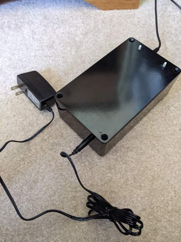
I soldered the jack onto a small dev board, bought a barrel plug power supply (I find those more reliable long-term than USB power), and put it all in a small project box from Mouser. The antenna seems to work well inside there. I was able to Dremel-in some holes for the power, sensor, and mounting standoffs. The box works well, but I think I’d 3D print something next time. I haven’t been out to my parents’ house yet, so haven’t been able to install or test the cell connection there. Hopefully it works there as well as here.
The inside of the finished project.
The finished box, closed. I still need to get a few screws to close this up.
Full Parts List
| Part | Source | Cost (USD, without tax and shipping) |
|---|---|---|
| Particle E-Series Eval Kit | Link | $92.03 |
| Seeed Current Sense Transformer | Link | $6.90 |
| 3.5mm Stereo Jack | Link | $.74 |
| Prototyping PCB | Link | $6.71 |
| AC Adapter | Link | $4.27 |
| Seeed 4 Pin Connector | Link | $1.50 |
| Seeed 4 Pin Cable | Link | $1.63 |
| Project Box | Link | $5.68 |
| Project Box Lid | Link | $4.42 |
| 10 Standoffs | Link | $3.76 |
| Total | $127.64 |