RasPi Flow Meter In A Pinch - Part 2
META: Part 1 describes the problem I’m trying to solve here.
I need a way to monitor water flow through my water filter over several days, and I don’t want to sit and watch it.
So - I took a Raspberry Pi I’ve got and a little Python and hacked a solution together. The basic idea was that I’d position a plastic cup below the output stream of the waste water, I’d put two wires into the cup, I’d put a voltage on one wire and attempt to see the voltage on the other. I’d use the Raspberry Pi to check for the voltage once per minute and log the status to a file with a timestamp. Later, I could graph the state of the voltage - DETECTED or NOT DETECTED - over time, and produce a graph showing when the waste water was running. With that I could even get an approximate flow rate waste water, if I wanted, by measuring how long it takes to output a liter of waste water and multiplying by run time.
First - the cup. The simple flow meter. I poked a hole in the bottom so water drains out slowly, and poked a couple holes through the sides to hold wires in position close to each other without touching. When water covers the wires current should be able to flow between them, when the water drains out current should stop flowing. If the waste water overflows the cup it will just run over and down the drain as it usually does. It takes about 30 seconds for water to drain from overflow until the wires are not conducting, and I was hoping to measure conductivity every minute, so my initial cup holes were close enough. The waste water runs quickly enough that the cup fills up in about a minute. This means that polling every minute should produce a graph that closely represents reality.

Next - the Raspberry Pi. I got Adafruit’s Pi Cobbler along with the Pi, which is a cleverly-named pinout that’s easy to plug into a breadboard. That plus this handy tutorial from Make made it really easy to write a little voltage tester. Here’s the code.
#!/usr/bin/env python3

import RPi.GPIO as GPIO
from time import sleep, ctime
import atexit

INPUT_PIN=21
POLL_PERIOD=60
LOG_FILE="/home/username/waterLog.csv"

def resetGPIO():
    GPIO.cleanup()

def setupGPIO():
    GPIO.setmode(GPIO.BCM)
    """ Set INPUT_PIN to pull-up, so the signal will be when it goes low
    That way, we won't potentially source a lot of current to ground with
    a positive voltage, and also just the ground of water might pull it down,
    which would indicate there's water in the cup (and therefore, is what we
    want)
    """
    GPIO.setup(INPUT_PIN, GPIO.IN, pull_up_down = GPIO.PUD_UP)

def pollForWater():
    with open(LOG_FILE, "a") as f:
        f.write(",".join((ctime(), str(GPIO.input(INPUT_PIN) == 0)))+"\n")

if __name__ == "__main__":
    atexit.register(resetGPIO)
    setupGPIO()
    while True:
        pollForWater()
        sleep(POLL_PERIOD)
So, now I connect the Pi to a ribbon cable, to a Pi Cobbler, to a breadboard, to two wires on pin 21 and a ground pin respectively. The other ends of the wires are not touching and are in the cup. A couple design choices - I could make the pin I’m using for input (pin 21) connect to the Pi via a pull-up or a pull-down resistor. These options, and the resistors, are built-in to the Pi and selectable in code.
I told pin 21 to use a pull-up resistor, but if instead I told pin 21 to use a pull-down resistor, it would normally rest at 0 V and I would detect a voltage (and thereby detect water) by connecting 3.3 V to the other wire. There’s a problem with that - I’m putting these wires in water and that will potentially introduce another “ground” connection. When the wires touch water, the 3.3 V wire would essentially be connected directly to ground, and then the Pi would try to provide a bunch of current, and that could be bad for the Pi.
I told pin 21 to use a pull-up resistor, so that means it normally rests at 3.3 V. It is connected through a good-sized resistor to 3.3 V, so when nothing is connecting the pin to ground or some other voltage, that resistor “pulls” the voltage on pin 21 up to 3.3 V. If something connects the pin to ground, the Pi will try to provide current again, just like before. However, in this case the good-sized resistor is in the way, between 3.3 V and ground, so the Pi won’t have to provide too much current to get everything to equilibrium. Some folks call this “current limiting” - the Pi is limited to how much current it can provide. A voltage source simply provides enough current to raise the voltage at its output to its set level. When that happens, all the currents and voltages balance out and everything reaches equilibrium and stays the same until some other thing happens to the circuit to throw everything out-of-balance. With pin 21 set as “pull-up”, even if the water introduces another ground, nothing bad should happen to the Pi.
Another design choice - I used Python’s “atexit” to cleanup the Pi’s GPIO port. The example website I linked to above simply put it after the “while True” polling loop. The problem with putting the GPIO cleanup after the infinite loop is that if you kill the program by pressing ctrl+c (or by any other means I can think of) the cleanup code never runs. Python just exits the program immediately. By registering the cleanup code with “atexit”, Python will run that cleanup code as the last thing it does whenever it possibly can. There are ways to kill the program where Python will bypass atexit, but all the common methods will let Python exit cleanly and cleanup the port. Port cleanup isn’t critical in my case - I’ve already got the simple ground protection setup I described above, but it can’t hurt, and if I ever just copy my old code into a new project I’ll be glad I did it correctly.
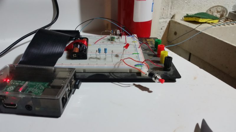
Um, that’s pretty much it. There’s some other stuff on the breadboard but it’s just an old circuit and is irrelevant here.
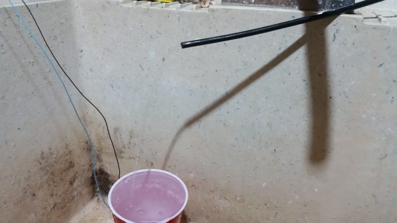
So, that’s what the setup in the sink looks like. The water is running out of the output here, it’s hard to see in the photo but there’s the shadow.
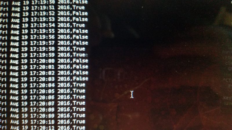
And here’s a photo of the screen. Because no screenshots for you. Just gonna take a photo and pretend like that’s cool. See how some say true and some say false? This was a test run, polling every second. When the wires are less than half-submerged they don’t provide a clean on/off signal to the Pi. That’s ok, this was a hack. When I poll only every minute the on/off signal gets much sharper.
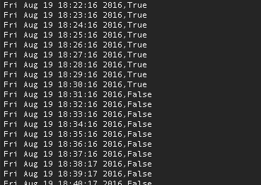
Actual data - a screenshot this time because we’re not savages. I filled up some containers at around 17:20, that caused the filter to start filtering and the waste water to start running, then the water ran until about 18:31, so about an hour. I would expect that the water doesn’t run again until late tomorrow at the earliest… We’ll see!
Comments:
RasPi Flow Meter In A Pinch – Part 1 | blog.notmet.net - Aug 5, 2016
[…] ← Previous Next → […]